Hacking a Wi-Fi Repeater
This article describes the process that led me to get the root shell on a device often used in common homes, the wifi repeater. The ability to manipulate these objects allows an attacker to load a backdoor or malware into the device’s firmware. For info on NANDO board, contact me on telegram: @jhacker91
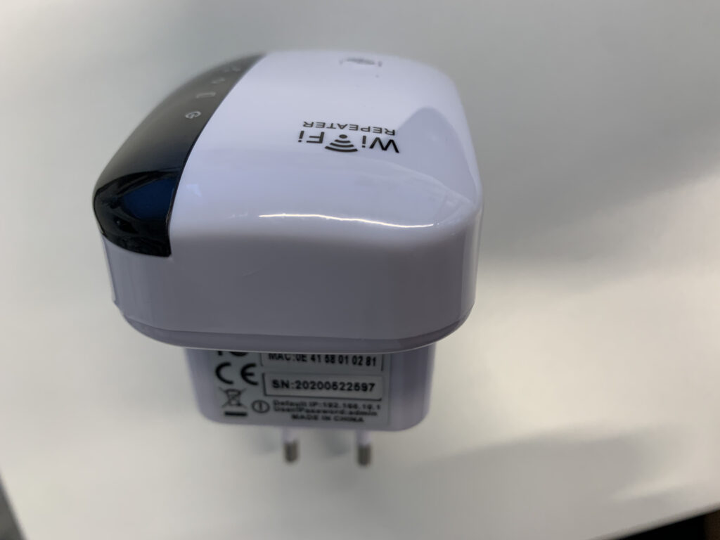
As object of study I chose a wifi repeater (shown in the following photo).
Before starting for convenience, using a soldering iron, I soldered 4 pins on the UART (in this case easily identifiable).
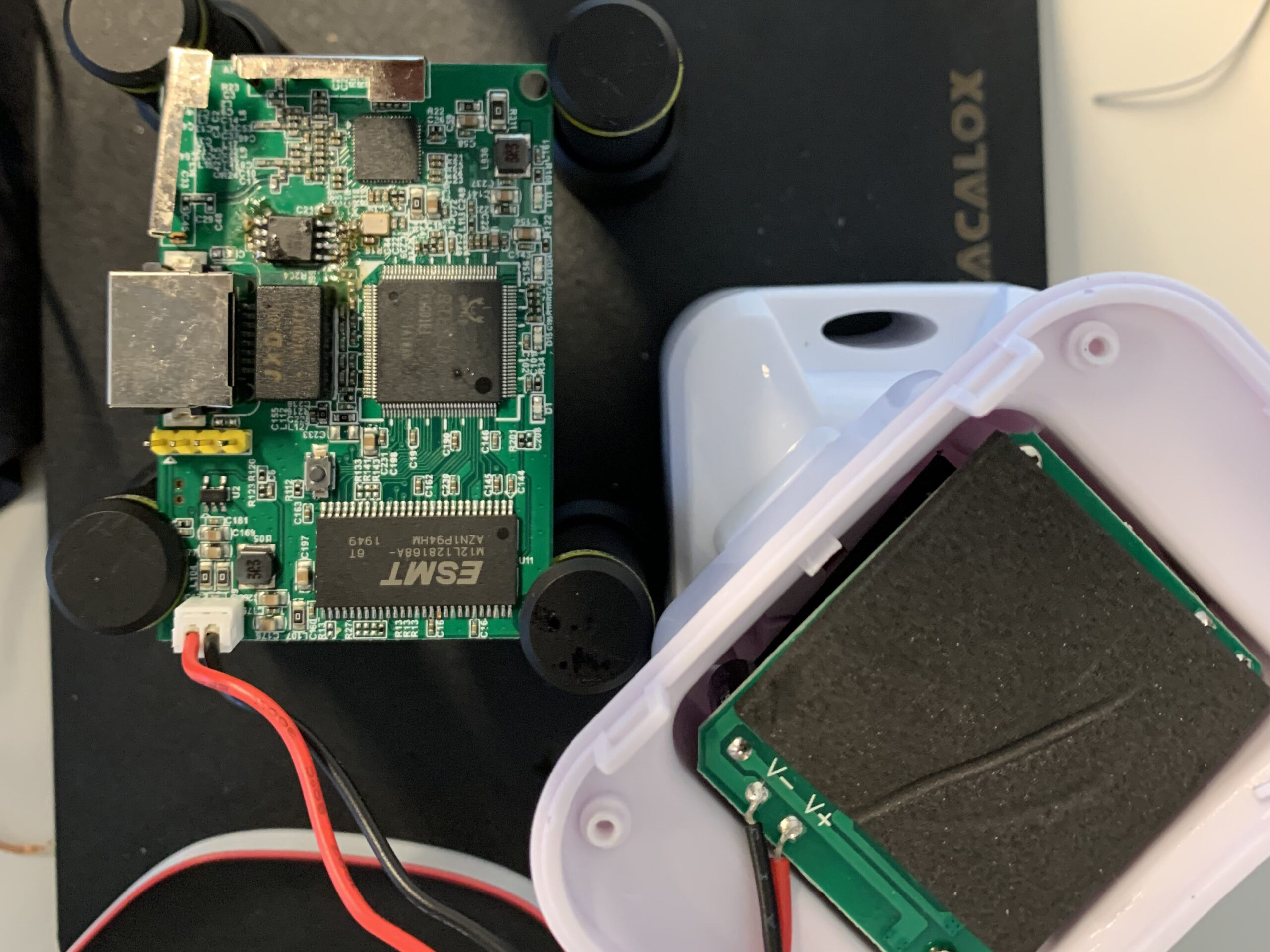
Analyzing the device you can see the presence of a UART (used as a debugging interface). Obviously we have to make some checks and for this reason I used a multimeter to look for the ground and analyze the voltage on the various pins. This step is crucial because it allows us to understand what is the ground (GND), what could be the TXD (used by the device to send data outside) and the RXD (used by the device to receive data from outside). Obviously, as indicated by the card, the VCC (power supply) is indicated by a small white arrow.
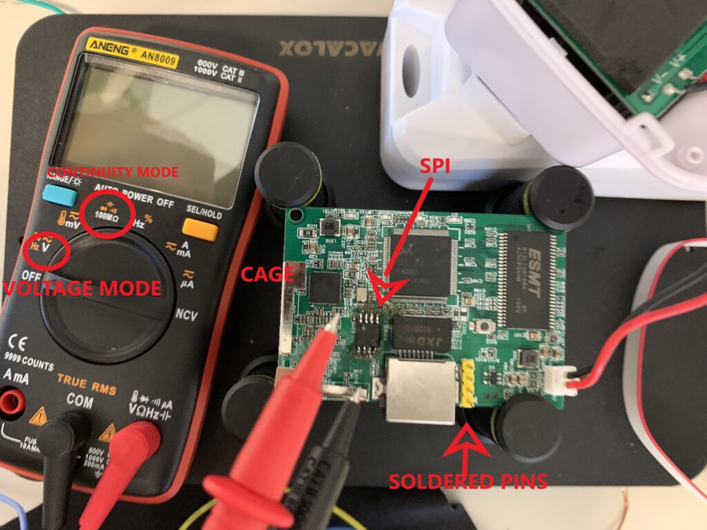
Warning: The device should always be turned off while using continuous mode
First of all I set the multimeter in “continuous” mode and I placed a multimeter pin on a cage (the metal parts on the board representing a GND) and the other cable on the pins of my interest in order to identify the ground (a continuous “beep” will be heard).
Now you have to set the multimeter in “V” mode to check the voltage of the other 3 pins and exclude the VCC (usually is the pin with the highest and stable voltage – 3.3V). For voltage it is necessary to turn on the device and with the multimeter place a pin of the multimeter on the GND (or on a cage) and one on the pins to be tested (it is essential to mark the voltages).
Warning: turn off the device
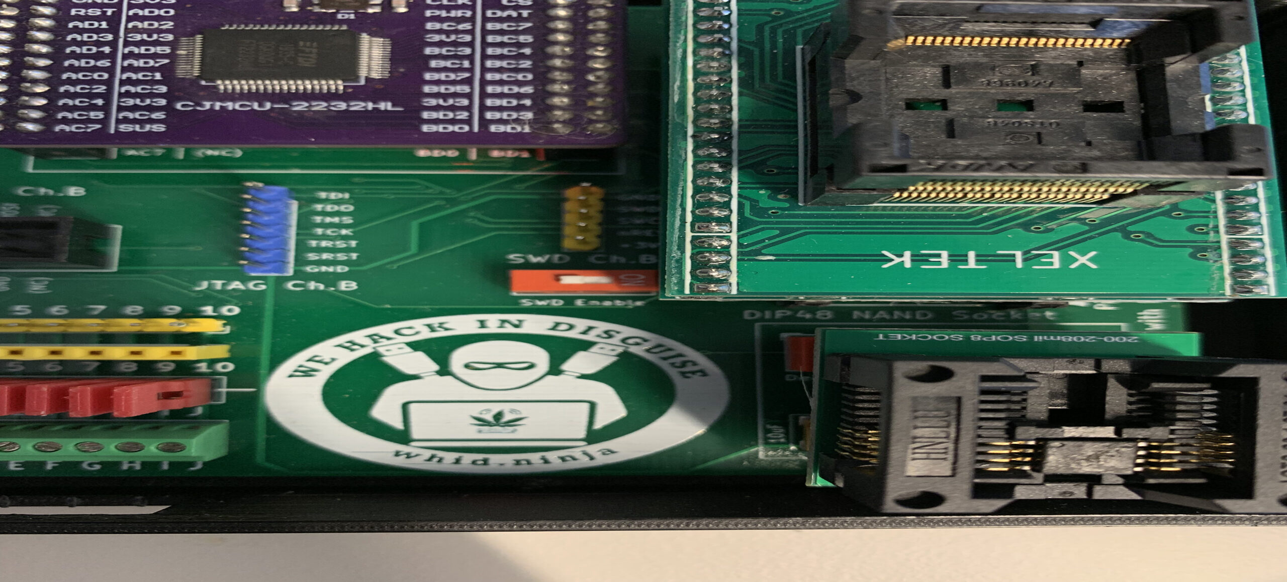
Once the ground has been identified, it has been possible to use the NANDO Board with the function of logic analyzer. The NANDO board (shown in photo) groups together all the useful features to analyze a hardware device for the collection and extraction of important information.
For NANDO board contact me on telegram: @jhacker91
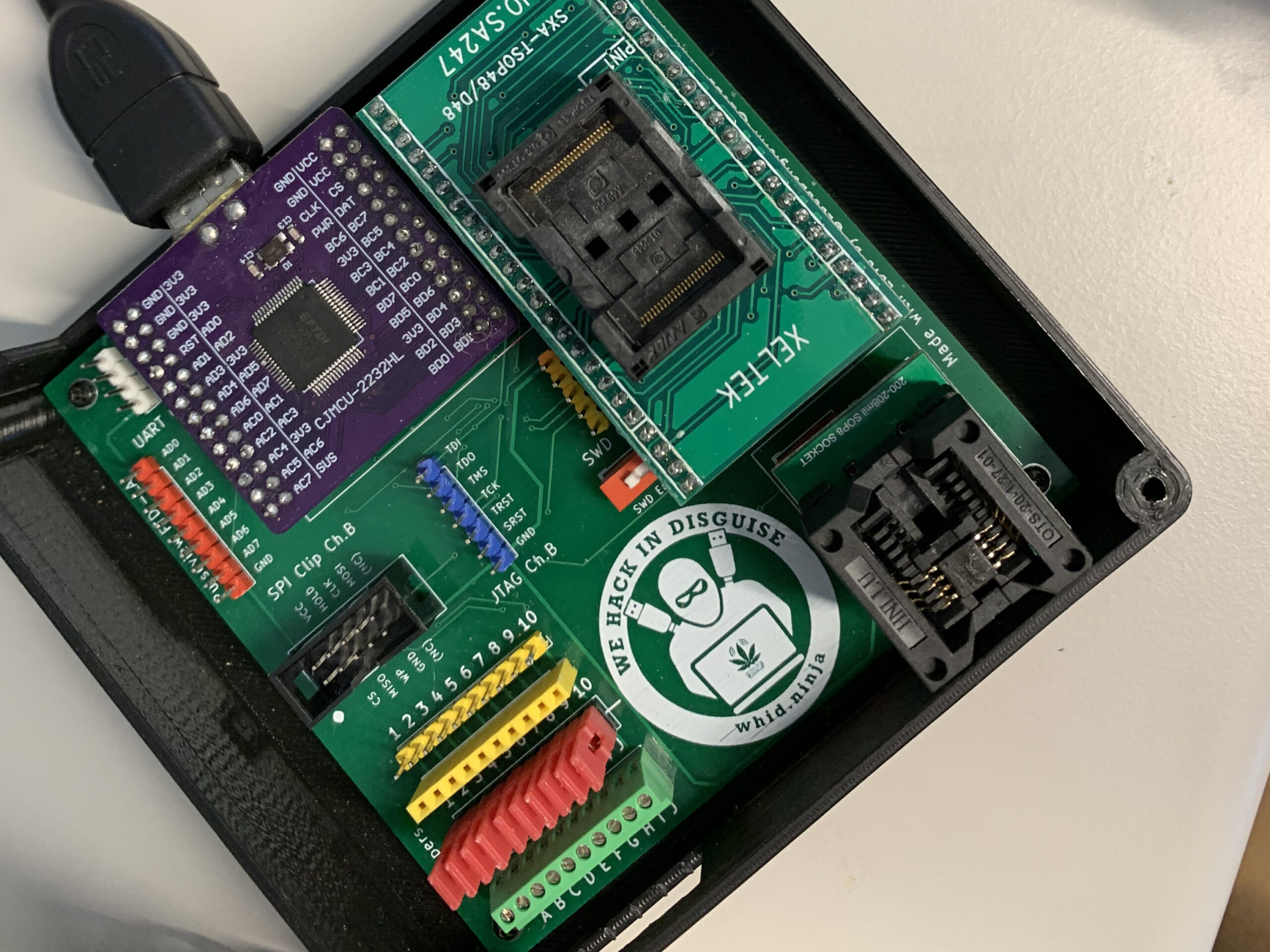
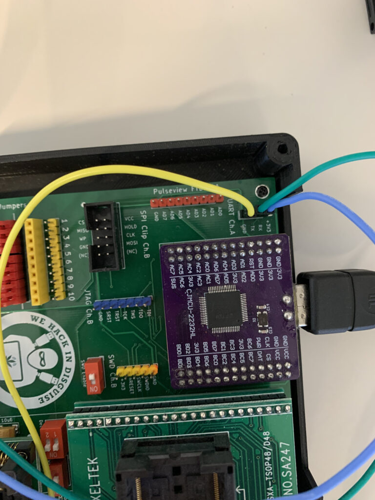
In order to use the logic analyzer we can use the “pulse view” section (orange). We connect the ground to the GND of the card to be analyzed (previously found) and to the GND marked on the pin of the NANDO board (GND). For GND I chose the yellow color.

The blue cable and the green cable are connected to the RXD and TXD candidates of the board and to the two channels of the “pulse view” of the NANDO board. Now we can connect the NANDO board via USB port to the pc and start “Pulse View”.
Warning: do not connect the pins to the VCC which is indicated with a white arrow
Once started “Pulse View” we have to configure the NANDO board by selecting the FTDI item (present in the menu near the red object). Select from the FTDI dropdown menu and click on scan. If everything goes well in STEP 4 the NANDO board will be identified in logic analyzer mode (as shown in the photo)
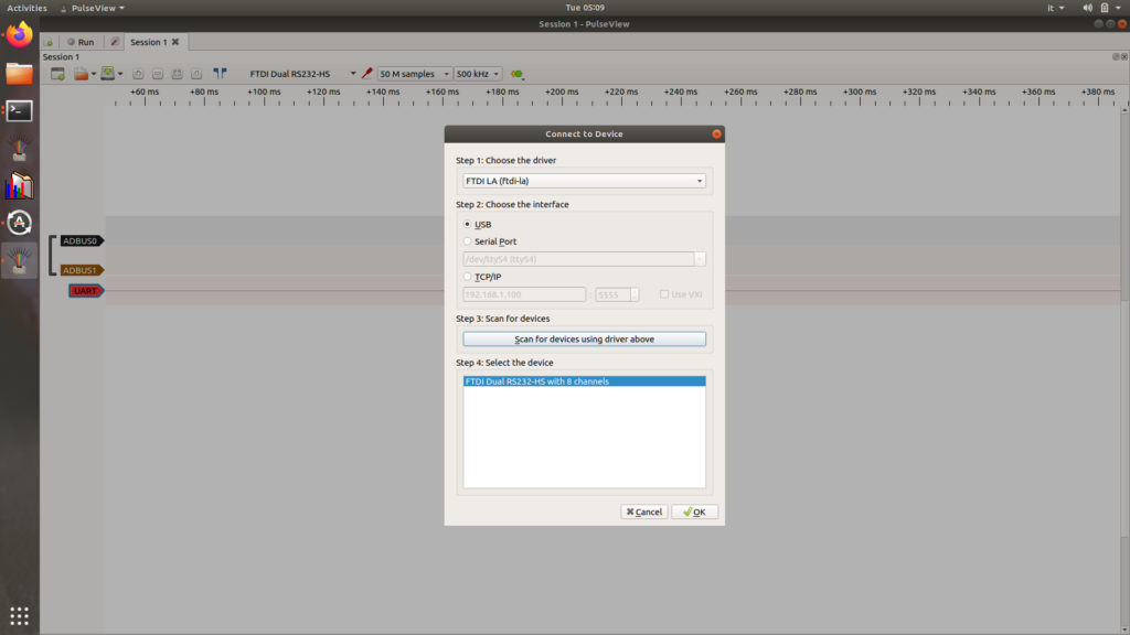
We select only ADBUS0 and ADBUS1 that match the pins connected to the NANDO board. By clicking on the green button we can also add the UART item. In the UART menu you have to set the canidate TXD and RXD.

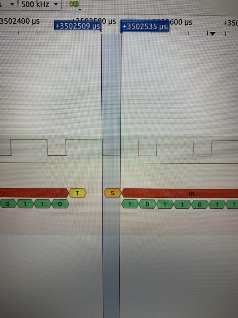
For the capture I chose 500khz and 100M of samples. Remember to set the field “data format” to ASCII. Start the capture by clicking on start button in the upper left corner and turn on the device immediately after. The logic analyzer displays information that may also be unreadable. In fact what you have to do is calculate the “baudrate”. To do this:
- You have to choose the smallest bit
- Read or calculate the width (in this case 3502535 – 3502509= 26)
- Calculate the baudrate using formula 1/ (Xe^(-6))
- In this case 1 / (26 e^(-6)) that is about 38400 (our baudrate)
Now, by setting in the UART channel settings, you can enter the correct baudrate and view all the bootloader information (In the green part you can see the bit by bit information).
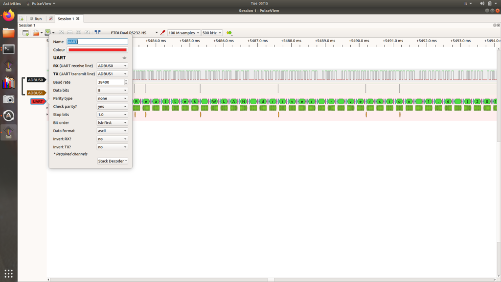
You can see that all the information has passed through the ADBUS0 channel which means that channel represents the TXD (because the device has sent all the information through that pin to the NANDO board).
At this point you have to use the UART function of the NANDO board (white color near Pulse View). Connect the NANDO board GND to the device GND, the NANDO board TX to the device RXD, and finally the NANDO board RX to the device TXD. This is because when the NANDO board sends a signal to the device, through its TX, it must pass through the receiving channel of the device itself (identified by RXD) and vivecersa.
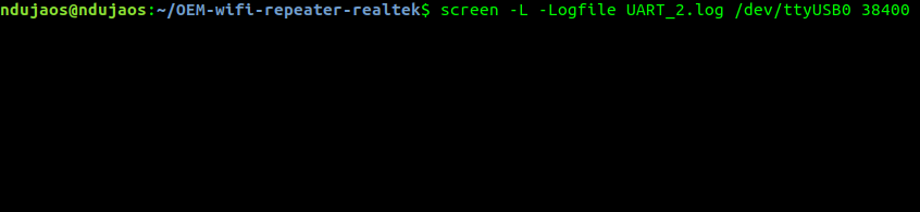
Now we connect the NANDO board to the pc, we use the command “screen /dev/ttyusb0 38400” (where ttyusb0 is the name of the connected NANDO board and 38400 is the baudrate).
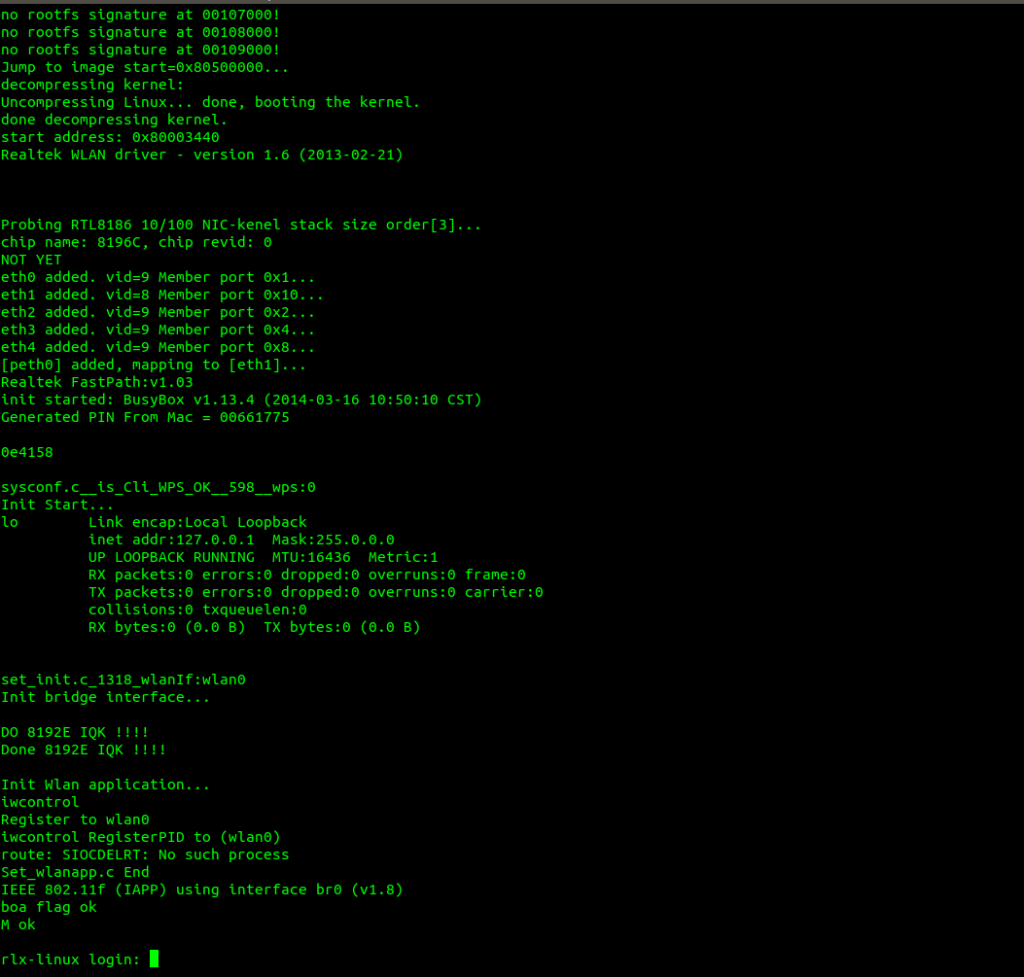
We turn on the device and we will see the whole sequence of bootloaders at the terminal. After the bootloader we get the shell but there is a login “rlx-linux login:”.
We can try brute force on the UART (on github there are many tools). You have to modify the script and run it. Unfortunately, it does not always work and for this reason we try to follow another path.
The process is to :
- Identify the SPI
- Remove the SPI
- Use the NANDO board to dump the firmware
After removing the SPI with the use of the soldering iron, identified in figure 3, it must be inserted in the NANDO board as in the following figure – bottom right (remember to disconnect the previously connected cables).
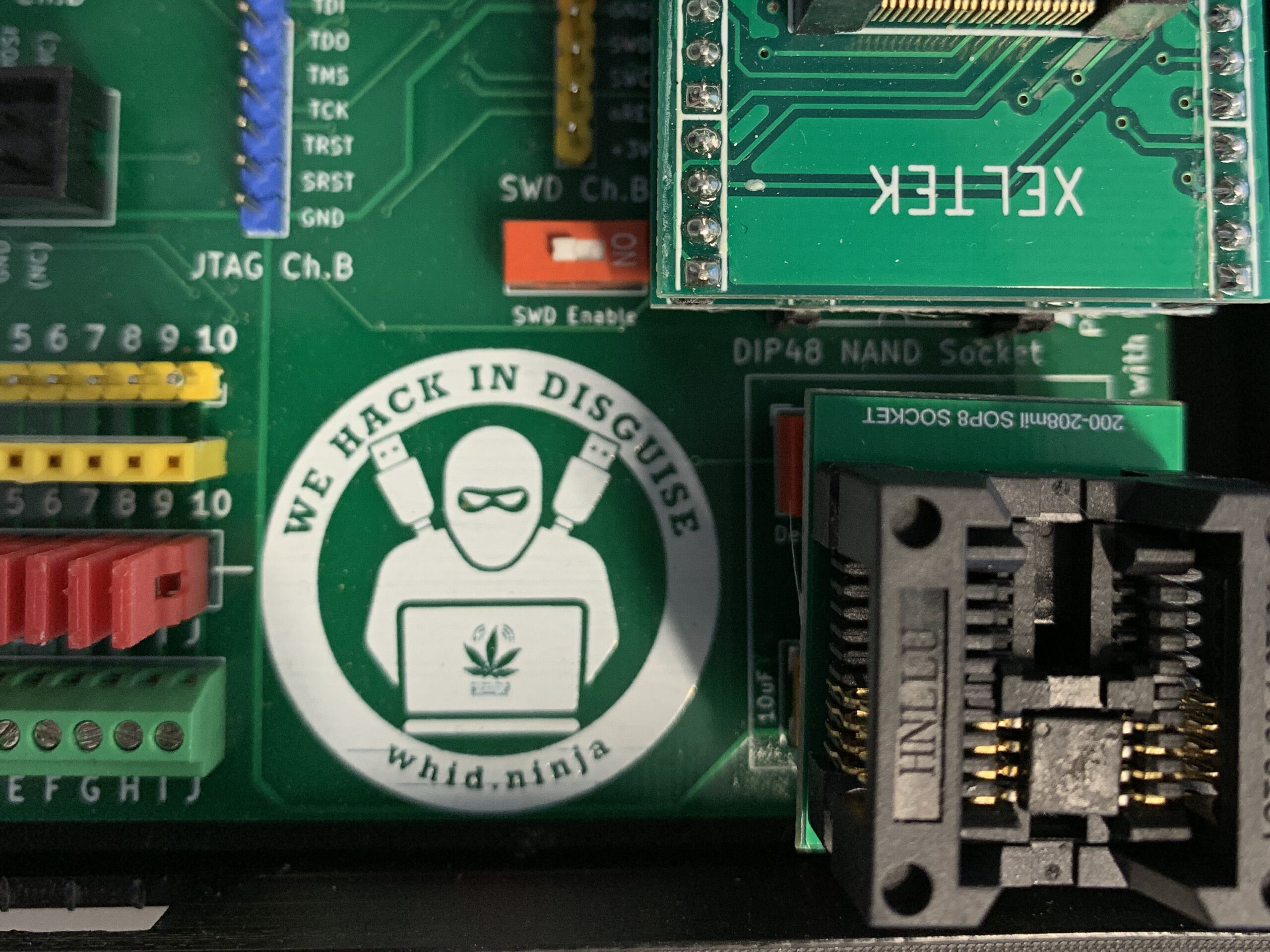
The NANDO board is always connected to the PC via USB.
We open the terminal and use flashrom to dump the firmware.
sudo flashrom -p ft2232_spi:type=2232H,port=B -r firmware-dump.bin
The “-p” command is used to identify the type of chip used on the NANDO board
The optional command -c is used in case you need to specify the SPI model. In this case flashorm returned a list of models. We can choose and indicate one by adding the command “-c MSD3332” (where MSD332 is the model name)
Using binwalk you can analyze packages.
The first command prints on screen the information about the firmware just dumped.
binwalk firmware-dump.bin
The second command extracts and saves the extracted information to a directory
binwalk -e firmware-dump.bin
Finally we can use the cat command to read the etc/passwd file
cat _firmware-dump.bin.extracted/squashfs-root/etc/passwd
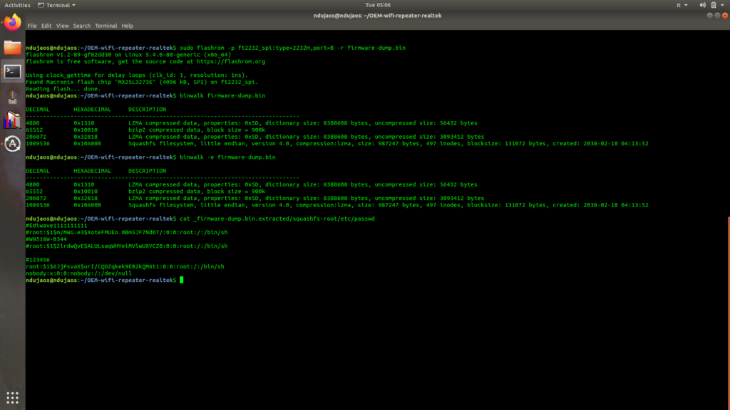
From the file you can read the password 123456.
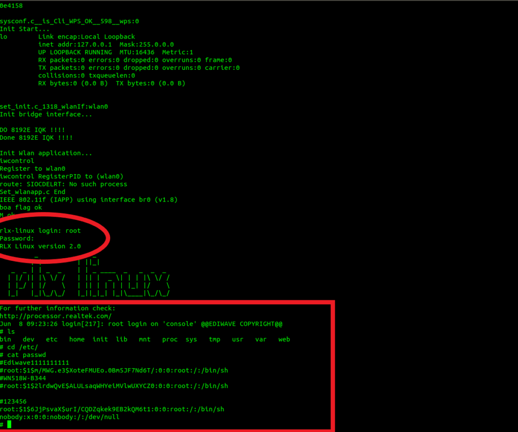
Now you have to weld the SPI back on the device and reconnect the UART to the NANDO board (as shown above). We use the command “screen /dev/ttyusb0 38400” again and turn on the device.
In the login interface we enter root as username and 123456 as password. We have full access to the system.
Thanks to:
Luca Bongiorni
Pasquale Turi
Matteo Mandolini
Bao Lei


